After hours of practice, here’s a method I developed to model bearings from the .dxf files found on manufacturers’ websites.
So the first thing to do is go to the link provided and download the .dxf file https://www.mcmaster.com/7804k106 for a shielded bearing.
Import the file into Blender. You might have to enable the addon “Import-Export: Import AUTOCAD DXF format (.dxf)” to be able to import .dxf files. Make sure the scaling is correct in the import window. Either check the scale in the import window or change it later in the Scene Properties.
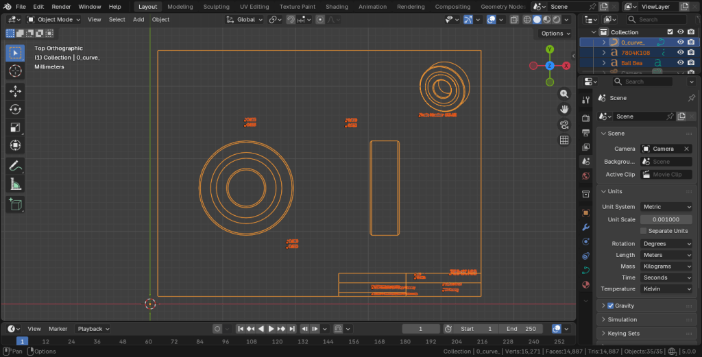
The .dxf is imported as a set of curves. The second thing I do is rename the “curve” to something more descript, such as “Bearing_Shielded_BD5” so I know it will fit an axle with bore diameter of 5mm. I highlight and delete the other curves in the outliner as all we will be using is the main stencil.
The next thing to do is convert the curve to mesh in the object menu. Then I go into edit mode and delete the border and the isometric stencil in the upper right corner. Take the side-view stencil and make it its own object using Separate, with the object center at what will be the top middle. Take the top-view stencil and put its origin at the center of the mesh. Do the same for the sideview. Send the side-view stencil to the origin of the top-view stencil, and rotate the side-view stencil so it is perpendicular to the other.
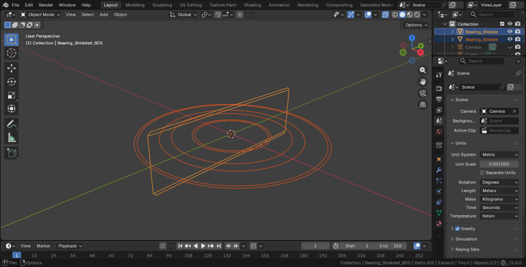
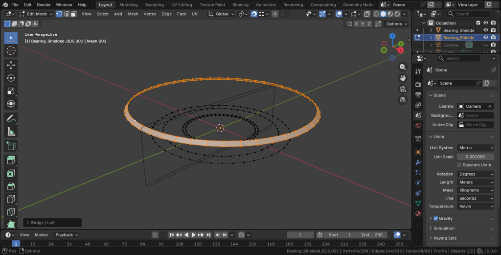
Now in edit mode for the top-view stencil, begin to edge-select each ring and move along the Z-axis, bridging them with LoopTools as you go. At some point you may want to change to X-ray mode or rotate the view to select multiple edge-loops. Using extrude and snap to vertex also works. You can also use Fill and select faces “Tris to Quads.”
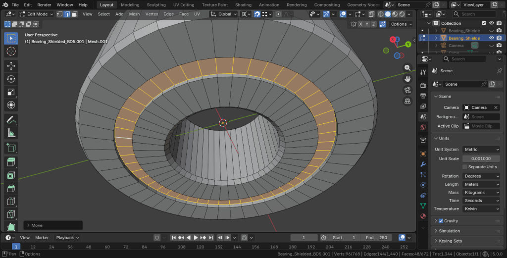
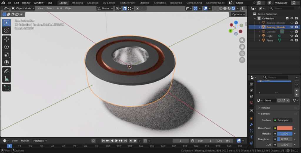
Shade Auto Smooth, add materials, and you’re done!