

After hours of practice, here’s a method I developed to model gears from the .stl files found on manufacturers’ websites.
Getting the Mesh Ready
Here’s a link to the gear we will be modelling: https://khkgears2.net/catalog2/DS0.5-16. Start off by downloading and importing the file, keeping in mind the scale of the scene so the part is the correct size.
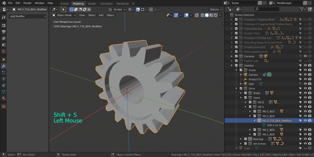
Before manually editing anything, let us ensure that the 3D cursor is set to the object origin. In object mode, set the 3D cursor to the object origin. We are making all of our rotations around the 3D cursor.
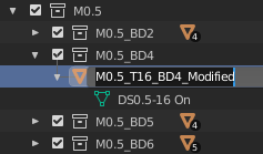
The gear in question has a Modulus of 0.5, 16 teeth, and a Bore Diameter of 3mm. Since I will be using it on a 4mm axle, I’m going to name the mesh M0.5_T16_BD4_Modified.
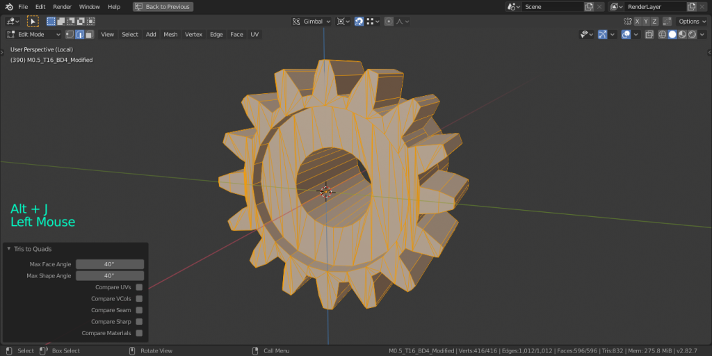
Taking into consideration that it’s almost always easier to model with quads instead of tris, the .stl desperately needs to be re-meshed. What a mess! There are many edges crossing each other with no intersection point, inconsistent geometry, overlapping faces. There is no way as of now to make or select edge-loops because Blender has very few adjacent quads to work with.
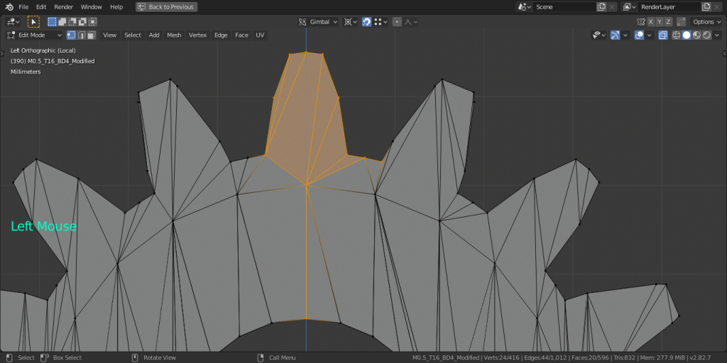
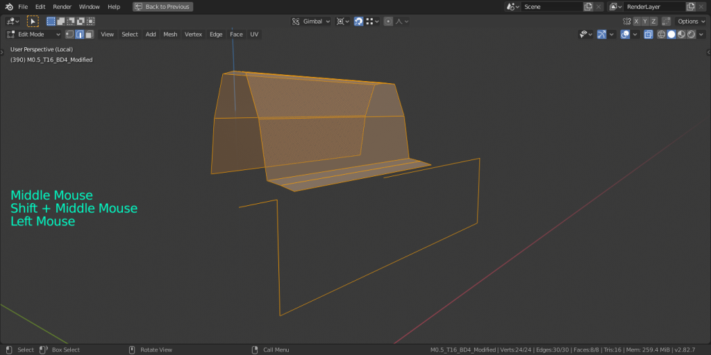
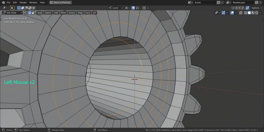
Whew, that should make things a little easier later on. Now, to tackle the inconsistent geometry. It would be nice to have each gear tooth be the same shape. What we can do is refine one gear tooth and clone it as many times as there are teeth on the gear. In edit mode with x-ray turned on, go to side view. Select the vertices of one tooth, it’s radial mesh, and the mesh between that tooth and the next one.

Invert the selection and delete the junky gear teeth surrounding the tooth we will be working on. Only the vertices of the original selection should remain.
What I do next is delete the edges inside the gear leaving only the perimeter of the gear and the inside radial. This leaves the essentially geometry needed to re-mesh the object. Here is what it looks like from an angle.
This next step is where things get a little confusing. It would be optimal to have two radials per each tooth since each tooth has two radial edge segments crossing one diametral edge segment. Let us take the one vertical inner radial, rotate it counter-clockwise by one quarter the circumference divided by the number of teeth. Then, extrude it clockwise by one half the circumference divided by the number of teeth. Do the last step one more time by pressing (Shift-R) and it should look like this.
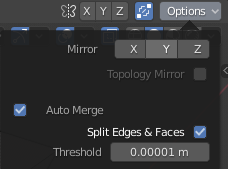
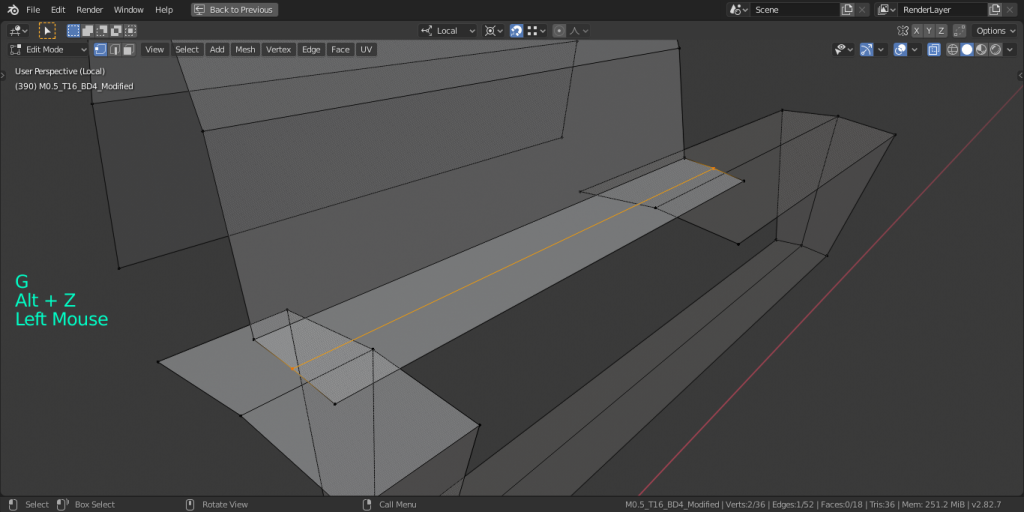
Now let’s mesh the inner faces with the outer perimeter. Make sure “Auto Merge Split Edges & Faces” is on for this next part. There should be only quads in this entire object so I shift this somewhat unnecessary edge along using edge slide. It will disappear allowing us to connect the gear and the radials with two quads on each side.
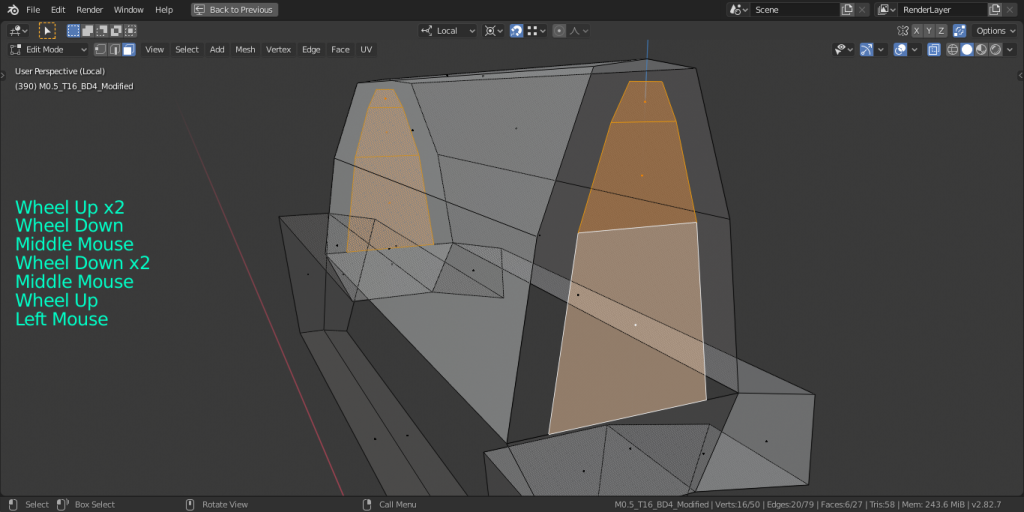
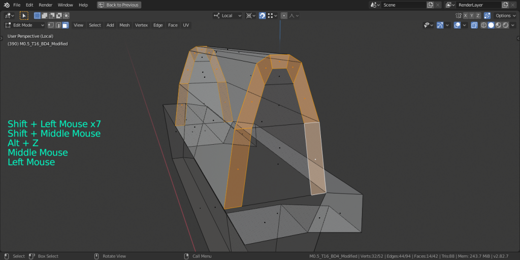
To fill in the gear tooth, I start from the bottom, subdividing the edges there into three edges each. Take the middle edges and extrude upwards three times. To be neat, clamp to the Z-axis, snap to the level vertices, and scale as you go.
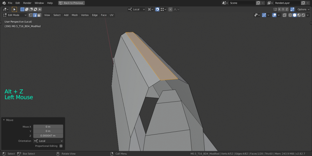
Take the uppermost edge and bevel it into two edges, moving it upward a little. All that’s remaining is to fill in the remaining faces.
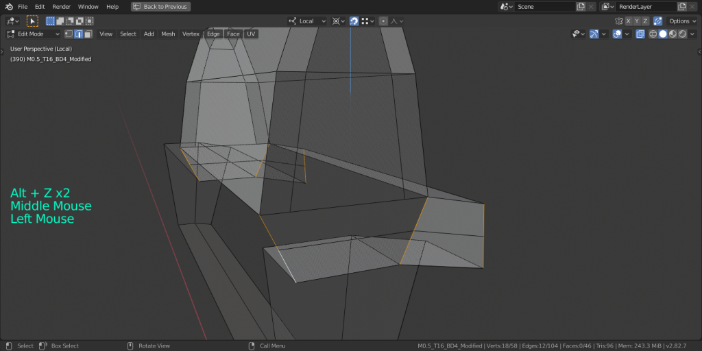
We must not allow messy geometry at the edges because we want it to tessellate without having to go back and alter the location of the vertices. I select these four edges and subdivide them once. This gives us a place to continue the edge loop that we created indirectly in the gear tooth.
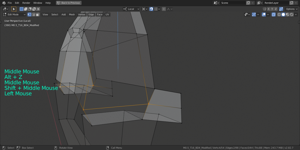
After that simply grab each vertex on the right side of the gear tooth and snap to the desired vertices. This would be a good time to save, if you haven’t already.
Revolving the mesh
Now, for the fun part!
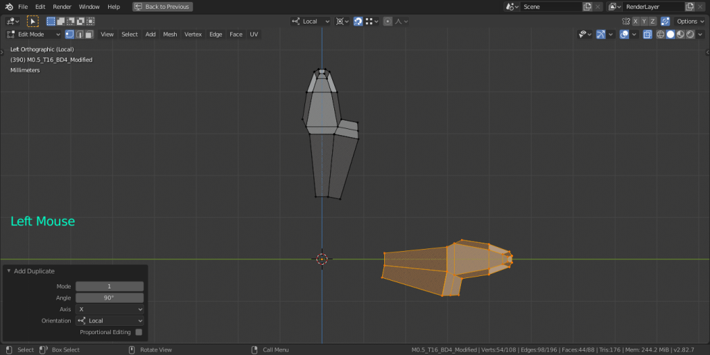
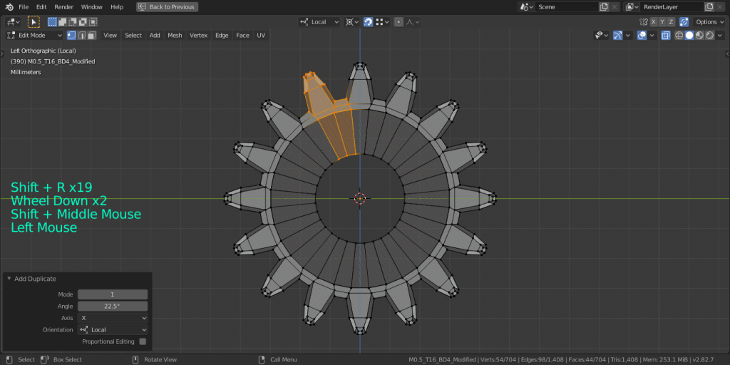
Select all vertices, duplicate them, and rotate them one quarter around the circle. Go into the little tab at the lower left and change the rotation to the circumference divided by the number of teeth. The left edge of the duplicate mesh should line up with the right edge of the original mesh.Without doing any other operations, use (Shift+R) to repeat the last commands until all teeth are done.
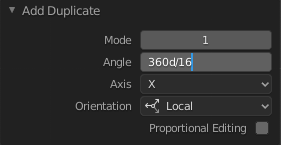
Changing data in this window does not count as additional commands.
Final touches
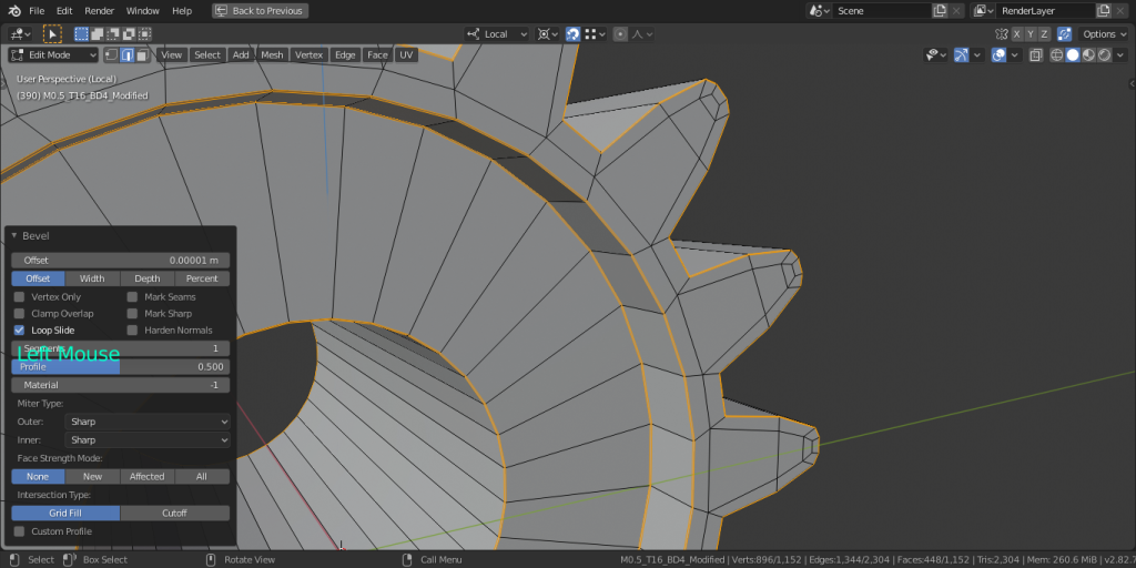
I like to select all, and recalculate normals at this point. Great, the basic mesh is complete! Select all edges (Ctrl+Alt+LMB) and give them a bevel of one segment.
Add edge loops (Ctrl+R) where there are large spans of radial edges. Great, that’s it for edit mode. Go into object mode, select shade as smooth, give it a subsurf modifier, a material, and check show object name in object properties.

If you want a part to machine with higher constraint control, you could choose use the bevel modifier on more edges instead of using a subsurf modifier. Since I won’t be machining these parts, and they are accurate visual representations only, in this case subsurf is more ideal for conserving system memory and providing a nicer render.
