
Since synthetic muscle is still technology of the future, and also out of my budget, I follow the current design trend to make wings flap using linear actuators. These can be pistons or pushrods linked to drive gears. Taking inspiration from mechanisms of a bygone era, I looked to the locomotive.
Since synthetic muscle is still technology of the future, and also out of my budget, I follow the current design trend to make wings flap using linear actuators. These can be pistons or pushrods linked to drive gears. Taking inspiration from mechanisms of a bygone era, I looked to the locomotive.
| 1. Eccentric Crank 2. Eccentric Rod 3. Reach Rod | 4. Lifting Link 5. Lifting Arm 6. Reverse Arm & Shaft | 7. Expansion Link 8. Radius Bar 9. Crosshead Arm 10. Valve Stem Guide | 11. Union Link 12. Combination Lever 13. Valve Stem 14. Valve Spindle |
For my design criteria I want wings that change shape as they flap to produce lift. With respect to real birds, the sweep of the wing should be midway transitioned both at the top (max dihedral) and bottom (max anhedral) of the flap cycle. At max and min sweep the wing should be at near horizontal angle traveling either up or down. I knew I needed two trigonometric waves out of phase by π/2, one to control the wing sweep, and one to control the vertical flap amplitude. How could I mount two free-swinging linear rods at different points on a drive wheel so that they don’t interfere with one another?


A part exists to solve this problem: the Eccentric Crank. Its function is to provide a mounting point for a second rod (reach rod) some degrees around the circle of the wheel such that the Eccentric Rod’s linear motion is out of phase with the Main Rod’s linear motion.
To be clear it is possible to connect different linear drives at different points along the same drive train, as I have seen other designers do. The benefit of having both connected at the same point along the drive train means they are locked in at the same RPM — meaning if a gear skips a tooth one rod will not go out of sync from the other.
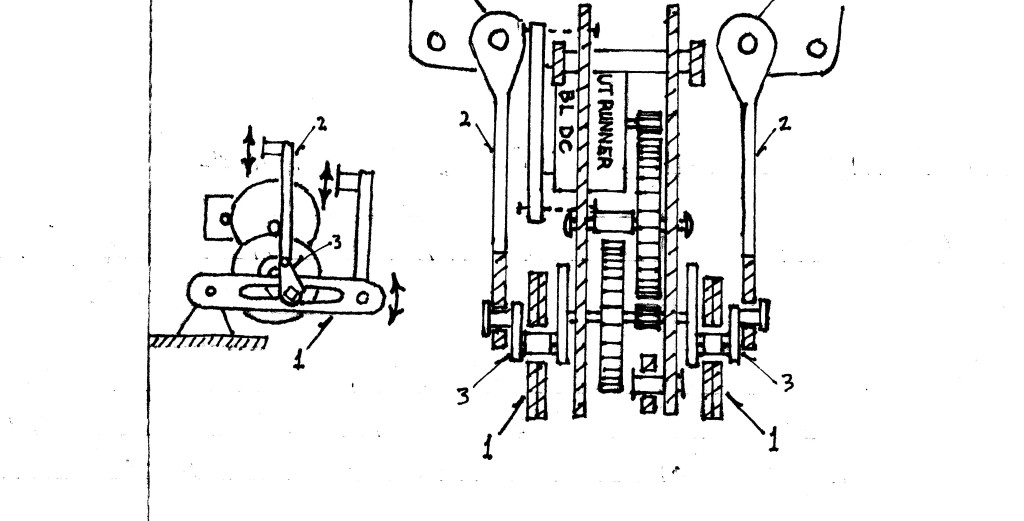
Here are sketches with few details, describing the basic elements of the gearbox I have in mind.
The slide rail (1.) bears most of the torsion from the wing root when weight and lift are at odds. I might have to make those linkages beefy and spring-assisted. The vertical sweep rod (2.) will move one-quarter revolutions ahead of the vertical flap rod (not pictured) and cause the wing to fold and sweep. Both the slide rail and the vertical flap rod are connected to the eccentric crank (3.) using lubricated bushings to decrease friction.
In other news, Blender revised its GUI six months ago and I was not hip to the changes until last week. This has been an opportunity to clean up my old project file as I become accustomed to the exciting new improvements. One of the biggest kickers was the fact that they brought more focus to the Outliner. Before 2.8, my project was organized into separate layers. Since the layer system no longer exists, I loaded in to find each layer’s items automatically sorted into Collections in the Outliner. I love it; it is so much easier to keep track of the visibility of object groups when we can view them in hierarchies.
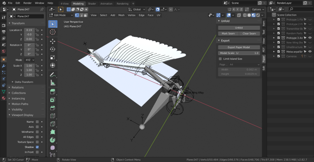
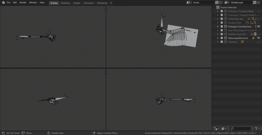
Next on the agenda is to finish restructuring and relabeling all of these layers. Then I might take a stab at modeling the gearbox.
